

How To Draw An Oblique Projection Cylinder
Three Dimensional Illustrations using Isometric and Oblique Project
Isometric Project
Figure 1 shows iii views of a cube in orthographic projection; the phantom line indicates the original position of the cube, and the full line indicates the position subsequently rotation well-nigh the diagonal AB. The cube has been rotated then that the bending of 45 ° between side AC1 and diagonal AB now appears to be 30° in the front elevation, C1 having been rotated to position C. It can clearly be seen in the end view that to obtain this result the angle of rotation is greater than 30°. Likewise, note that, although DF in the front summit appears to be vertical, a cross bank check with the cease elevation will ostend that the line slopes, and that point F lies to the rear of point D. Even so, the front superlative now shows a iii dimensional view, and when taken in isolation it is known as an isometric projection.
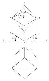
Effigy one - Cube in Orthographic Projection
This type of view is unremarkably used in pictorial presentations, for example in car and motor-bicycle service manuals and model kits, where an associates has been 'exploded' to indicate the correct order and position of the component parts. It will be noted that, in the isometric cube, line AC1 is drawn as line AC, and the length of the line is reduced.
Effigy two shows an isometric calibration, which in principle is obtained from lines at 45° and 30° to a horizontal axis. The 45° line XY is calibrated in millimetres commencing from point X, and the dimensions are projected vertically on to the line XZ. By like triangles, all dimensions are reduced by the same corporeality, and isometric lengths tin can be measured from point Ten when required. The reduction in length is in the ratio
isometric length = cos 45° = 0.7071
true length cos 30° 0.8660
= 0.8165
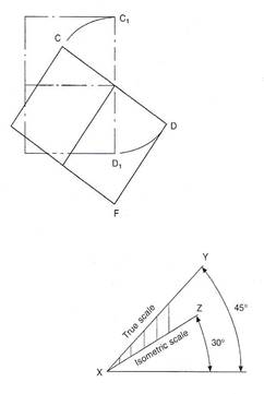
Figure ii - Isometric Scale
Now, to reduce the length of each line by the utilise of an isometric calibration is an interesting bookish exercise, just commercially an isometric project would be drawn using the true dimensions and would then exist enlarged or reduced to the size required.
Note that, in the isometric project, lines AE and DB are equal in length to line Advertising; hence an equal reduction in length takes identify along the apparent vertical and the two axes at 30° to the horizontal. Note likewise that the length of the diagonal AB does not alter from orthographic to isometric, but that of diagonal C1D1 clearly does. When setting out an isometric projection, therefore, measurements must be fabricated but along the isometric axes EF, DF, and GF.
Effigy iii shows a wedge, which has been produced from a solid cylinder, and dimensions A, E,and C indicate typical measurements to exist taken along the principal axes when setting out the isometric project. Any curve can be produced by plotting a succession of points in space after taking ordinates from the X, Y, and Z axes.
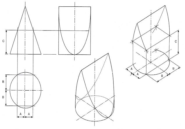
Figure iii - Construction Principles for Points in Infinite, with Complete Solution
Figure 4(a) shows a cross-section through an extruded alloy bar: the views (b), (c), and (d) give alternative isometric presentations drawn in the 3 principal planes of project. In every case, the lengths of ordinates OP, OQ, P1, and Q2, etc. are the same, but are positioned either vertically or inclined at 30° to the horizontal.
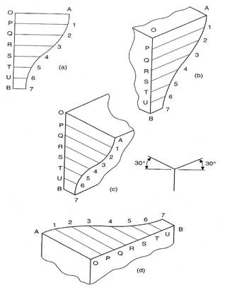
Figure 4 - Views (b), (c) and (d) are Isometric Projections of the Section in View (a)
Effigy 5 shows an approximate method for the structure of isometric circles in each of the iii major planes. Note the position of the points of intersection of radii RA and RB.
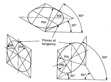
Figure 5 - Structure of Isometric Circles
The structure shown in Effigy 5 tin be used partly for producing corner radii. Figure vi shows a small-scale block with radiused corners together with isometric projection, which emphasises the construction to find the centres for the corner radii; this should be the first part of the drawing to exist attempted. The thickness of the block is obtained from projecting dorsum these radii a altitude equal to the block thickness and at thirty°. Line in those parts of the corners visible backside the front face, and complete the pictorial view by adding the connecting straight lines for the outside of the profile.
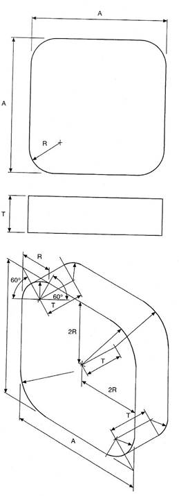
Figure vi - Isometric Constructions for Corner Radii
In the gauge construction shown, a pocket-size inaccuracy occurs along the major centrality of the ellipse, and Figure seven shows the extent of the error in conjunction with a plotted circle. In the vast majority of applications where consummate just small circles are used, for instance spindles, pins, parts of basics, bolts, and fixing holes, this fault is of piffling importance and tin be neglected.
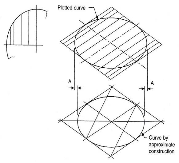
Figure 7 - Relationship between Plotted Points and Constructed Isometric Circles
Oblique Project
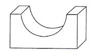
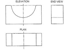
Effigy eight shows office of a plain begetting in orthographic project, and Figure 9 show alternative pictorial projections.
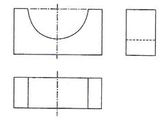
Effigy viii - Plain Bearing in Orthographic Projection
It will be noted in Figure 9 that the thickness of the bearing has been shown by projecting lines at 45° back from a front elevation of the bearing. Now, the picture on the right of Figure 9 conveys the impression that the begetting is thicker than the true plan suggests, and therefore in the picture to the left of Figure 9 the thickness has been reduced to one half of the actual size. The pic on the left of Figure 9 is known as an oblique projection, and objects, which have curves in them, are easiest to draw if they are turned, if possible, so that the curves are presented in the front elevation. If this proves impossible or undesirable, then Figure ten shows part of the ellipse, which results from projecting half sizes dorsum along the lines inclined at 45°.
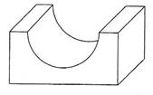
Effigy 9 - Alternative Pictorial Projects
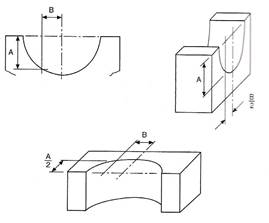
Effigy 10 - Function of the Ellipse
A small die-cast lever is shown in Figure 11, to illustrate the use of a reference aeroplane. Since the bosses are of different thicknesses, a reference plane has been taken along the side of the spider web; and, from this reference aeroplane, measurements are taken forrad to the boss faces and backwards to the opposite sides. Note that the points of tangency are marked, to position the slope of the web accurately.
With oblique and isometric projections, no allowance is made for perspective, and this tends to give a slightly unrealistic result, since parallel lines moving back from the plane of the paper do not converge.

Effigy 11 - Die-Cast Lever
Further information regarding pictorial representations, reference can be made to BS EN ISO 5456-3. The Standard contains details of Dimetric, Trimetric, Cavalier, Cabinet, Planometric and Perspective projections.
Isometric Drawing
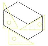
Isometric drawing is a form of pictorial cartoon based on lines at 30 degrees from the horizontal. Figure 12 shows the bones thought when making an isometric drawing of a rectangular prism. Vertical lines are drawn with the aid of the correct angle of a set square, lines at xxx degrees are fatigued with the aid of a thirty,60 ready square.
When constructing an isometric cartoon, all measurements must be made forth the isometric axes - either the vertical lines or along the 30 degree lines. This applies even when amalgam arcs or curved lines in isometric drawings. Figure xiii shows the method of finding the sizes along the isometric axes for the structure of Effigy 14. Figure 15 shows how lines, which are not along the isometric axes, must be constructed from measurements taken along the axes.
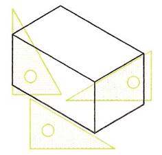
Figure 12 - Isometric Drawing of a Rectangular Prism
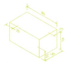
Figure 13 - Sizes must exist taken along Isometric Axes
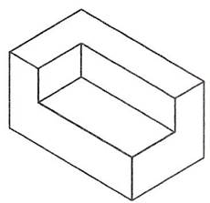
Figure xiv - Finished Isometric Cartoon to the Sizes in Figure 13

Figure 15 - Sloping Lines - Sizes must be measured along Axes
Constructing Isometric Curves
Figure 16 shows how an isometric circle is synthetic:
- Depict a circle of the required diameter - the lower drawing of Effigy 16. Draw vertical lines - a, b and c - at any spacings beyond the circumvolve.
- Draw the two middle lines for the circle at 30 degrees each mode - the upper drawing of Effigy 16.
- Mark off the lengths Oa, Ob and Oc, taken from the circumvolve, forth ane of the isometric centrelines, each side of the centre O. Draw 30 degree lines through the points a, ring c.
- Each side of the centre line from a, b and c marker off the lengths a1, b2 and c3 along the 30 degree lines from a, b and c.
- Mark the lengths Od each side forth the centre line in the isometric drawing.
- All necessary points for cartoon the isometric circumvolve have now been establish. Draw a off-white curve through the points to complete the required isometric circle - which is an ellipse.
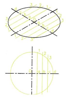
Figure sixteen - Method of Constructing an Isometric Circumvolve
Effigy 17 shows a similar construction for circles in other isometric positions.
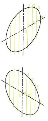
Figure 17 - Other Positions for Isometric Circles
Figure eighteen is an case of a uncomplicated isometric drawing and Figure xix some other instance which includes isometric 'circles'.
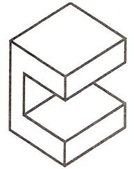
Figure xviii - Simple Isometric Drawing
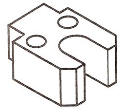
Figure 19 - Elementary Isometric Cartoon Involving Circles
Note: The reader is brash not to use isometric ellipse templates until he or she has had sufficient practise in constructing isometric ellipses every bit shown above.
Exploded Isometric Drawing
A Simple Exploded Isometric Drawing
Figure xx is a uncomplicated 'exploded' isometric drawing; its parts have been 'exploded' along the isometric axes.
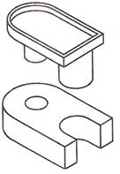
Figure 20 - Uncomplicated Exploded Isometric Cartoon
An Exploded Isometric Drawing
Figure 21 is an exploded isometric cartoon of a fork end, showing the two parts – its end piece and its rodin an exploded position. The rodis shown pulled out from the END forth an isometric 30 degree axis. A rear view of the terminate pieceis included to show that the rodfits into a hole in its dorsum face. To construct the drawing:
- Working to the sizes given with Effigy 21, describe the end piece, remembering that the chamfer sizes must be taken forth the isometric lines.
- Construct the rodusing the method shown in Figure 16 to draw the curves of the isometric circles.
- Line in the required drawing outline and erase any unwanted lines.
- Add a title cake, which includes your proper name and the championship EXPLODED ISOMETRIC DRAWING in 8 mm high capital letters.
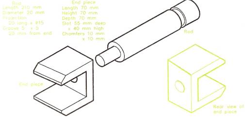
Figure 21 - Exploded Isometric Drawing
Freehand Drawing
For preparing the layouts for orthographic drawings and for the necessary training work when designing, freehand drawing (or sketching) is a skill, which should be gained by practice. HB or B grade pencils are more suitable for freehand work than the 2H or 3H pencils, which are used for technical drawings fabricated with the aid of instruments. If isometric and foursquare grid papers are available, a good tip is to start learning how to depict freehand sketches on grid papers. Such filigree papers tin can be purchased in A4 or A3 sheets with the grid lines printed in dark-green or blueish - either square grids or isometric grids are available. The spacing of the grid lines is either at 10 mm intervals or at 5 mm intervals. However, when you have gained sufficient skill in freehand drawing with the aid of grid papers, it is all-time to then sketch on plain paper without the grid lines. The examples given in this book are for freehand sketching on either the lines of orthographic projection or isometric drawing.
An instance of a freehand drawing of a pedestal mounting as grooming for the layout of the drawing before amalgam the views of an orthographic projection are shown in three examples - Figure 22 on an A3 sheet of 10 mm square grid paper, Effigy 23 on a smaller sheet of grid newspaper and Figure 24 on plain paper without a filigree. Figure 25 shows a freehand isometric drawing on isometric grid paper with the filigree at x mm spacing. Figure 26 is a similar freehand drawing on isometric lines on obviously newspaper without grid lines.
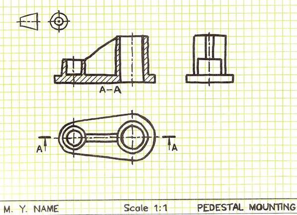
Figure 22 - Freehand Drawing on an A3 Canvas of 10mm Foursquare Filigree Paper
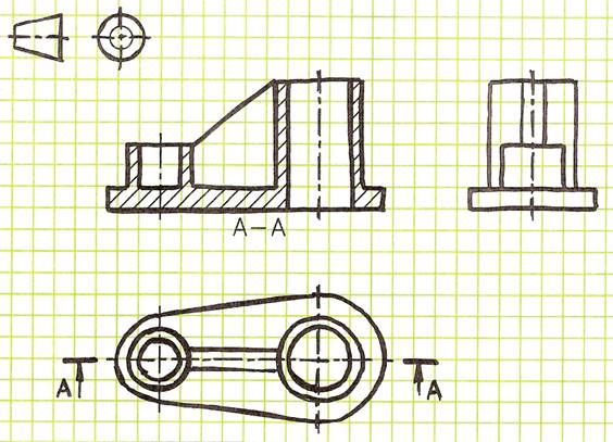
Figure 23 - Example of a Freehand Cartoon on a 10mm Square Grid Paper
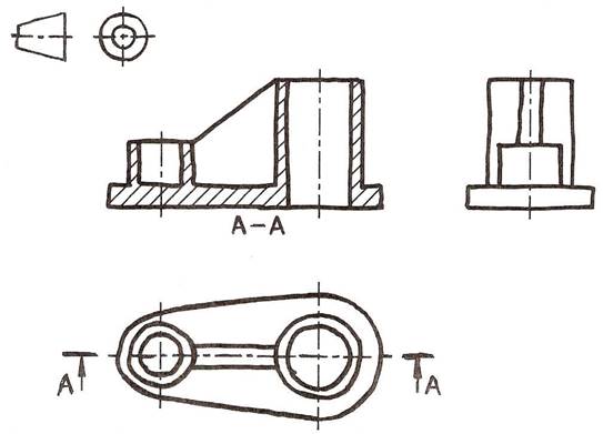
Figure 24 - Freehand Drawing of an Orthographic Projection on Manifestly Paper without Filigree Lines
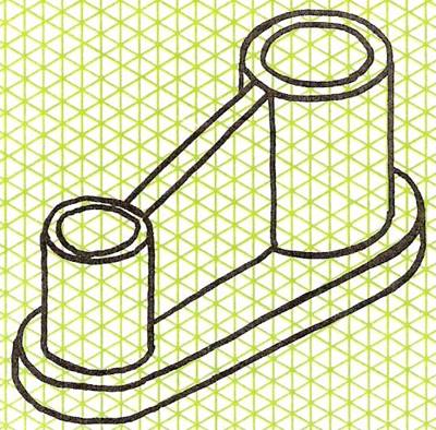
Figure 25 - Freehand Isometric Drawing on Isometric Grid Paper with Line Spacing at 10mm
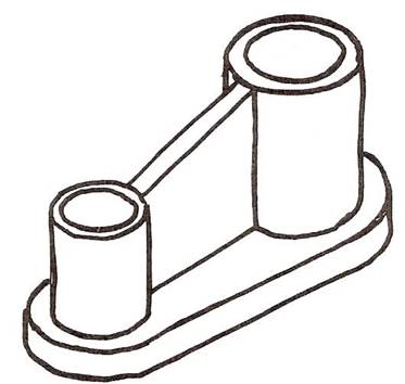
Figure 26 - Freehand Drawing on Isometric Lines on Plain Paper without Grid Lines
The 4-Arcs Method of Drawing Isometric Circles
Figure 27 shows the method of cartoon an isometric circle with the help of instruments.
- Draw the 30 degree lines which represent the square circumscribing the circle. Thus lines AB, BC, CD and DA are all at 30 degrees and are notwithstanding length.
- Draw the diagonal AC.
- Draw BF and DE in which E is the middle betoken of AB and F is the centre bespeak of CD.
- With G, the intersection of AC and BF, every bit a centre, draw an arc of radius GF.
- Draw an arc of center H and radius HE.
- With centre B and radius BF draw an arc.
- With centre D and radius DE draw an arc.
- You have now drawn the four arcs to consummate the structure.
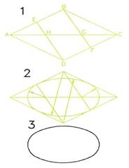
Figure 27 - 4-Arcs Method of Constructing an Isometric Ellipse
Effigy 28 shows similar methods for isometric four-arcs in unlike isometric positions.
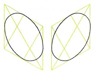
Figure 28 - 4-Arcs Method used in Other Isometric Positions
Note : This method does not produce accurate isometric circles (ellipses), but is sufficiently authentic for the construction of isometric ellipses up to about 50 mm in diameter. For larger isometric ellipses, it is advisable to use the more than right method, involving the plotting of points along the ellipse curve and then drawing a fair curve through the points and then obtained. If the 4-arcs method is used with larger ellipses, the resulting drawing will have a distorted appearance.
Figure 29 is an example of an isometric drawing, which involved the structure of ellipses on three faces using the iv-arcs method of construction.
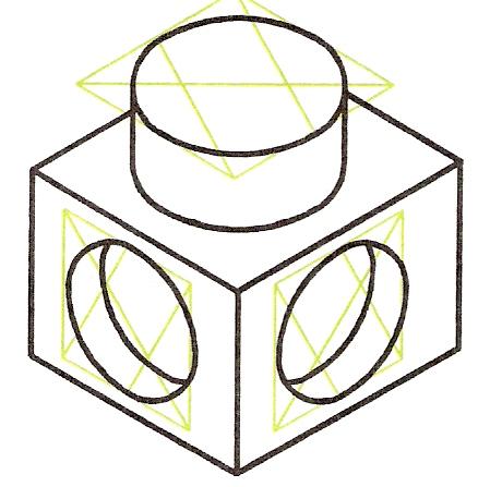
Effigy 29 - Example of an Isometric Drawing Involving Isometric Ellipses on Three Faces using the iv-Arcs Method of Construction
Cartoon Isometric Curves
The method of cartoon ellipses (from circles) in isometric drawings as shown in Figure 16 is suitable for the drawing of more than complicated shapes and curves in isometric drawings as shown in Figure 30. This illustration shows:
- A Forepart view of the object to be drawn with vertical lines forth its outline - these lines are often referred to as ordinates.
- The vertical lines accept been transferred to the isometric cartoon with the same spacings between the verticals along the 30 caste centrality.
- The lengths of the lines have been transferred from the Front view onto the isometric cartoon.
- 30 caste lines of the length of the thickness of the shaped object have been drawn from the upper ends of each ordinate in the isometric View.
- A off-white curve has been drawn through the points so obtained.
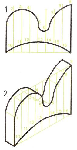
Figure xxx - Example of Drawing an Isometric Curve using the Ordinate Method of Construction
Estimated 1 and Ii-Point Perspective Drawing
If you look carefully at any object, lines along its sides appear as if they are inclined to vanish towards what is known as a Vanishing Signal or V.P. This illusion can be readily seen by looking forth a pair of straight railway lines. The idea of 5.Ps is the basis of the 2 geometrical methods - one-point (or unmarried-indicate) and 2-point perspective drawing.
Note : True perspective drawing involves a tertiary V.P., but 3-indicate perspective cartoon is beyond the scope of a book of this nature. Yet it must be remembered that one-bespeak and two-indicate perspective drawing do not give true perspective and so may at times appear inaccurate. The ii methods practice, however, provide an excellent and easy method of drawing very well suited to the preparation of drawings for designs.
Estimated One-Point Perspective Drawing
Effigy 31 is an example of a one-point perspective of a stepped platform. Note the post-obit:
- The position of the single 5.P. can be in any position above, to the right, to the left or below a Front view of the object being drawn. If the 5.P. is beneath, so a view from below the object will be drawn.
- From the Front view draw lines to the V.P.
- Complete the rear of the object with lines between the lines to the V.P. Lengths along the lines are estimated.
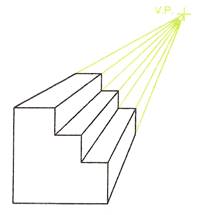
Figure 31 - Example of a One-Signal Perspective Drawing
A second case is given in Figure 32, involving a semi-circular office. In this instance a line from the middle of the semi-circle has been drawn to the V.P. in order to find the heart of the arc at the rear of the object.
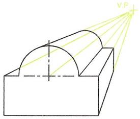
Figure 32 - Ane-Point Perspective Cartoon that Includes an Arc
Estimated 2-Point Perspective Drawing
In 2-point perspective two V.Ps are positioned. They must exist in line with each other horizontally, but tin be above or beneath the object being drawn. The two-point perspective drawing Figure 33 was drawn as follows:
- Position the ii V.Ps in appropriate positions.
- Depict a line representing the front end edge of the object - this line to be of the same length every bit the total acme of the object.
- Draw lines from meridian and bottom of the line to the two Five.Ps.
- Gauge the depth of the object on the right-hand side; depict a vertical line betwixt the 2 lines to Five.P.2.
- From the intersection of this line with the line to the V.P.ii depict some other line to the V.P.one.
- Continue in this manner to consummate the perspective drawing.
Note : The positions of the 5.Ps are critical to the advent of the final cartoon, so must be chosen with care to avoid distortion. Some experimenting is advisable. It is only necessary to draw the outline for the perspective to make up one's mind whether or not your cartoon is going to await as if it is distorted.
The methods of 1 and ii-point perspective are very suitable for freehand drawing, particularly when preparing work for designing.
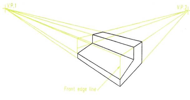
Figure 33 - Example of Two-Point Perspective
Self Assessment
Questions on Background Notes – Module vi.Unit ten
i. In diagram course or simply past word explain the main differences between
Orthographic Projection and Isometric Drawings.
Answers to Question one. Module half-dozen. Unit 10
Orthographic Projection:
Effigy nineteen: Orthographic Project Shows Iii Basic Views.
Isometric Drawing:
Isometric cartoon is a class of pictorial drawing based on lines at thirty
degrees from the horizontal. Vertical lines are drawn with the aid of
the right angle of a set square, lines at 30 degrees are drawn with the
aid of a xxx,60 set foursquare.
When constructing an isometric cartoon, all measurements must exist
fabricated along the isometric axes – either the vertical lines or along the
 30 degree line.
Figure xx: Isometric Drawing of a Rectangular Prism.
Source: http://local.ecollege.ie/Content/APPRENTICE/liu/metalfab_notes/module6/Isometric%20and%20Oblique%20Drawing_M6_U10.physician
If you are the author of the text above and you not agree to share your cognition for teaching, research, scholarship (for fair apply as indicated in the United states of america copyrigh depression) please send us an east-mail and nosotros volition remove your text chop-chop. Fair utilize is a limitation and exception to the exclusive right granted by copyright constabulary to the author of a creative work. In United states copyright police, off-white apply is a doctrine that permits express apply of copyrighted textile without acquiring permission from the rights holders. Examples of fair use include commentary, search engines, criticism, news reporting, research, teaching, library archiving and scholarship. It provides for the legal, unlicensed citation or incorporation of copyrighted material in another author's work under a four-factor balancing test. (source: http://en.wikipedia.org/wiki/Fair_use)
The information of medicine and health independent in the site are of a full general nature and purpose which is purely informative and for this reason may non replace in any example, the quango of a physician or a qualified entity legally to the profession.
The texts are the holding of their corresponding authors and nosotros give thanks them for giving us the opportunity to share for gratuitous to students, teachers and users of the Web their texts will used but for illustrative educational and scientific purposes only.

Source: https://www.summaryplanet.com/engineering/Isometric-and-Oblique-Projection.html
Posted by: lupientorty1994.blogspot.com
0 Response to "How To Draw An Oblique Projection Cylinder"
Post a Comment